This is a desktop app I am writing to make it easy to manage Dexter. A high priority for me is making the app be able to update itself so that I can keep everyone up to date with my latest improvements. So I am working on this part first. There is a lot of behind the scenes stuff that you can't really see in the video. That is why I added a section showing how much source code I've written so far :)
Monday, December 29, 2014
Wednesday, December 3, 2014
Dexter bootstrap video
TLDR: Dexter booting up for the first time in a new environment
This is a video of Dexter bootstrapping itself from a new SD card image. It reboots twice (after creating a partition dedicated to holding .ldimg files), then copies an .ldimg file from a USB drive to its SD card in order to achieve good performance.
What does this mean for you?
It means that Dexter is closer to being able to fully auto-configure itself so that a human being needs to do less in order to use Dexter. This is a high priority for me (to make Dexter as easy as possible to use).
Tuesday, October 28, 2014
Dexter update
Hi all,
You've probably been wondering where my Dexter progress has gone since I haven't posted anything here in a long time.
Unfortunately, having a newborn baby is taking its toll on me and I haven't spent ANY time working on Dexter for several weeks. At CAX, I alluded to this during my presentation when I said that my wife was going to have a baby and it would impact my time to work on Dexter. Our baby just turned 3 months old and is still waking up 2-3 times in the middle of the night to eat and until that stops, I will need to use my spare time to catch up on sleep. I just wanted to let everyone know what is going on. The good news is that this 'wake up in the middle of the night' condition is ALWAYS temporary and goes away. :)
Tuesday, October 14, 2014
Dragon's Lair ticks
I haven't posted a blog entry in a while and this is something pretty interesting that I'd like to have saved somewhere so here goes.
Dragon's Lair's scene data has a concept of 'ticks' which roughly map to clock ticks generated by the hardware. They are used to determine how long scene segments should last.
One issue with Dragon's Lair hardware is that the clock tick frequency differs slightly across different revisions of the hardware. Dragon's Lair's ROM program does a speed test upon boot-up to determine whether the hardware clock is faster, normal, or slower. The result of this speed test is displayed in the scoreboard as a 1 (faster), 2 (normal), or 3 (slower).
Here is the disassembled code that documents this speed test:
ROM:11BA SpeedTestLoop: ; CODE XREF: START+7B j
ROM:11BA ; START+88 j ...
ROM:11BA ld hl, SpeedTest_A001 ; when this loop starts for the first time, HL is FFFF, DE is FFFF, and BC is 0000
ROM:11BD bit 1, (hl)
ROM:11BF jr nz, SpeedTestGotIrq ; if this is non-zero, it means IRQ has been triggered
ROM:11C1 inc bc
ROM:11C2 jr SpeedTestLoop ; when this loop starts for the first time, HL is FFFF, DE is FFFF, and BC is 0000
ROM:11C4 ; ---------------------------------------------------------------------------
ROM:11C4
ROM:11C4 SpeedTestGotIrq: ; CODE XREF: START+78 j
ROM:11C4 res 1, (hl) ; clear IRQ flag
ROM:11C6 inc d
ROM:11C7 ld a, 48 ; don't start tracking IRQs until we've got 48 of them
ROM:11C9 cp d
ROM:11CA jr c, loc_11D1
ROM:11CC ld bc, 0
ROM:11CF jr SpeedTestLoop ; when this loop starts for the first time, HL is FFFF, DE is FFFF, and BC is 0000
ROM:11D1 ; ---------------------------------------------------------------------------
ROM:11D1
ROM:11D1 loc_11D1: ; CODE XREF: START+83 j
ROM:11D1 ld a, 50
ROM:11D3 cp d
ROM:11D4 jr nz, SpeedTestLoop ; when this loop starts for the first time, HL is FFFF, DE is FFFF, and BC is 0000
ROM:11D6 ld a, c
ROM:11D7 ld (unk_E035), a ; least significant digit from BC
ROM:11DA srl a
ROM:11DC srl a
ROM:11DE srl a
ROM:11E0 srl a
ROM:11E2 ld (unk_E034), a
ROM:11E5 ld a, b
ROM:11E6 ld (unk_E033), a
ROM:11E9 srl a
ROM:11EB srl a
ROM:11ED srl a
ROM:11EF srl a
ROM:11F1 ld (unk_E032), a ; most significant digit from BC
ROM:11F4 ld a, 0Ah
ROM:11F6 cp b
ROM:11F7 jr c, BcGreaterThanOrEq0A00 ; if BC >= 0x0A00 then branch
ROM:11F9 set 3, (hl) ; set bit 3 of A001 to indicate that speed test's result is 'faster'
ROM:11FB ld a, 1 ; speed test got a '1' result
ROM:11FD jr SpeedTest1Or2Result ; set bit 0 of A001 to indicate the speed test's result is a 1 or 3
ROM:11FF ; ---------------------------------------------------------------------------
ROM:11FF
ROM:11FF BcGreaterThanOrEq0A00: ; CODE XREF: START+B0 j
ROM:11FF ld a, 15h ; check to see if BC >= 0x1500
ROM:1201 cp b
ROM:1202 jr c, SpeedTest3Result ; branch if BC >= 0x1500
ROM:1204 ld a, 2 ; speed test got a '2' result
ROM:1206
ROM:1206 SpeedTest1Or2Result: ; CODE XREF: START+B6 j
ROM:1206 set 0, (hl) ; set bit 0 of A001 to indicate the speed test's result is a 1 or 3
ROM:1208
ROM:1208 ExitSpeedTest: ; CODE XREF: START+CC j
ROM:1208 ld (unk_E038), a ; set speed test result to scoreboard
ROM:120B set 2, (hl) ; set bit 2 of A001 to indicate that the speed test is finished
ROM:120D jr BootPhase2 ; play 'move' beep
ROM:120F ; ---------------------------------------------------------------------------
ROM:120F
ROM:120F SpeedTest3Result: ; CODE XREF: START+BB j
ROM:120F res 0, (hl) ; clear bit 0 to indicate that speed test result is slower
ROM:1211 ld a, 3 ; display a 3 on scoreboard
ROM:1213 jr ExitSpeedTest ; set speed test result to scoreboard
ROM:1215 ; ---------------------------------------------------------------------------
So what does the result of the speed test mean for the ticks?
If the speed test got a 1 (faster) or a 2 (normal), then every 31st tick is dropped. If the speed test got a 3 (slower) then every 255th tick is dropped. Here is the code which handles this:
ROM:1922 ld hl, SpeedTest_A001 ; bit 0: 1=drop every 31st tick (speedtest result was 1 of 2), 0=drop every 255th tick (speedtest result was 3)
ROM:1922 ; bit 1: (during speed test) 1=IRQ has been triggered, 0=IRQ has not been triggered yet
ROM:1922 ; bit 2: 1=normal operation, 0=speedtest active
ROM:1922 ; bit 3: 1=speedtest got a '1' (faster), 0=speedtest got a '2' or '3' (just right or slower respectively), see 11F9
ROM:1925 bit 0, (hl)
ROM:1927 jr z, DropEvery255thTick ; drop every 255th tick
ROM:1929 ld b, 31 ; drop every 31st tick
ROM:192B jr UpdateGlobalTickCounter
ROM:192D ; ---------------------------------------------------------------------------
ROM:192D
ROM:192D DropEvery255thTick: ; CODE XREF: IRQ+107 j
ROM:192D ld b, 255 ; drop every 255th tick
ROM:192F
ROM:192F UpdateGlobalTickCounter: ; CODE XREF: IRQ+10B j
ROM:192F ld hl, GlobalTickCounter_A000 ; keeps a count of how many ticks we've processed so that we can drop ticks from time to time
ROM:1932 ld a, (hl)
ROM:1933 inc a ; increment tick counter
ROM:1934 ld (hl), a
ROM:1935 cp b ; do we need to drop this tick?
ROM:1936 jr nz, UpdateAllTickCounters
ROM:1938 xor a
ROM:1939 ld (hl), a
ROM:193A jp PostCountersUpdate ; we go here after the tick counters have been updated
ROM:193D ; ---------------------------------------------------------------------------
ROM:193D
ROM:193D UpdateAllTickCounters: ; CODE XREF: IRQ+116 j
Additionally, the IRQ service routine will periodically skip certain work if the speed test was a '1' in order to 'slow down' the timer in software.
Therefore, to reliably understand how many seconds a certain number of 'ticks' mean in the Dragon's Lair move data, one can apply this algorithm:
Assume that the hardware clock 'ticks' every 32.768 milliseconds and that the CPU is 4 MHz. This will yield a speed test result of 2 (normal).
extraTicks = ticks / 30; /* (no remainder, for example, 31/30 would be 1, not 1.0333) */
adjustedTicks = ticks + extraTicks;
seconds = (adjustedTicks) * 0.032768;
Wednesday, September 17, 2014
Monday, September 1, 2014
Java annoyances
So I've wanted to learn java for years and am kinda forcing myself to do the desktop portion of the Williams IC Tester in java.
Quick take: C# is a better language in pretty much every way (which makes sense since MSFT shamelessly copied java and improved upon it). And in some ways, C++ is better than java, which is why I am writing this blog post.
I discovered (re-discovered) that java does not have unsigned data types. Everything is signed. If you google for information about this, you will find java apologists demanding people to justify why unsigned data types are needed. I found this attitude somewhat absurd.
Being an emulation author and a machine language enthusiast, unsigned data types are a no-brainer. The benefit of unsigned types is that the maximum size of the type in question is doubled from the signed version (in the positive direction). This benefit is something I take advantage of so often that I take it for granted. Here is a quick example.
An unsigned byte has a range of 0-255, while a signed byte is -128 to 127. I work with bytes a lot, by default, I expect to have a max upper range of 255. I've expected this for years (many many years). In fact, I can't remember the last time where I willingly chose to use a signed byte for any meaningful work. If I am going to use a signed number for any purpose, I will almost always use whatever the native CPU is optimized for which means on a 32-bit CPU, I would use a 32-bit signed integer, on a 64-bit CPU, I would use a 64-bit signed integer, etc. I can't think of any practical use for a signed byte when it's so common/easy to use an 'int'. So the fact that java only supports signed bytes is a major blunder in the design, IMO.
Now, you may be saying that I can just ignore the sign for many operations and I will still get the same result. This is somewhat true, or rather, would be somewhat true, if java didn't get in my way.
In C++, I am used to doing something like this:
uint8_t u8 = 0xFF; // C++ assigns this to have a value of 255
int i = u8;
^ - I would _always_ expect i to have a value of 0xFF after performing this operation. It is a no-brainer.
However, to my dismay, I discovered that java does the wrong thing here:
byte u8 = 0xFF; // java assigns this to have a -1 value, even though it has a datatype called 'byte' hur hur
int i = u8; // now i is set to -1 also (0xFFFFFFFF) instead of 255 (0xFF).
To workaround this poor language design, one has to do this:
byte u8 = 0xFF;
int i = u8 & 0xFF; // hurrr hurrrrrr
Now it works correctly because I manually hacked the value to have the proper sign. Nevermind that performing an extra AND for no practical reason wastes CPU cycles (admittedly not that many) that wouldn't have to be wasted if I could simply tell the language that u8 was supposed to be unsigned and to treat it accordingly.
What I've got from reading about java is that if you want to deal with unsigned types, you need to use a signed type that is bigger to spoof the unsigned type. So if you want to represent an unsigned byte, you'd use a short, if you wanted to represent an unsigned short, you'd use an int, if you wanted to represent an unsigned int, then you'd have to go crazy and use a long. It's really pathetic for any "serious" language to have to require this kind of hackery.
This doesn't mean that I've given up on java. After all, C# is proprietary/MSFT so it's not really available on other platforms (don't get me started on mono). So java still has its place, but I am not going to be fleeing C++ any time soon since java hasn't given me a great reason to do so.
Friday, August 29, 2014

Thursday, August 28, 2014
First Dexter rev 3b prototype finished

Friday, August 22, 2014
Soldering the next round of Dexter prototypes
The new board without any soldering done.

The new board with all of the surface mount ICs soldered in. A few solder bridges, but no big deal. All in all, the soldering took me about 2 hours. I can't wait to have a machine assemble these :)

Thursday, August 14, 2014
Williams IC tester PCBs arrived, partially soldered
The Williams IC tester PCBs showed up today. I decided to try a new way to solder by just putting solder paste on the four corners of each IC. The purpose of this is twofold:
- Lay the solder paste down fast
- Have the ICs align themselves during the "melting" process
As you can see, they are aligned pretty well. They have solder bridges, as I expected, but these will actually be useful because I can take an iron and drag the bridges across the unsoldered pads to quickly get the rest of the pads soldered, then use a wick to clean up. I am liking this rapid DIY approach :)
Wednesday, August 13, 2014
Troubleshooting Galaxy Ranger
I've been trying to troubleshoot a non-working Dexter setup with Galaxy Ranger and ended up writing some Z80 assembly language to modify the ROM for greater visibility. This little code snippet will print the LD-V1000 status to the screen. I am putting it here so I can find it again later if I need it :)
$D46 and $D47 should be changed from 0xCD 0x15 to 0x60 0x5B. The new code should be put at location $5B60 (lives on the second EPROM) in memory which is filled with 0xFF's on the stock ROMs.
; modify Galaxy Ranger to display LD-V1000 status code during "WARM-UP"
org 0x5b60
start:
; preserve registers
push hl
push bc
push af
; set target pointer
ld hl, 0xF169 ; right above $F189 'warming up' text (each row is 0x20$
ld a, (0xc800) ; LD-V1000 I/O flip-flop
ld b, a
; isolate top nibble
srl a ; A >>= 4
srl a
srl a
srl a
cp 0xA ; Acculumulator - 0xA is what?
jr c, Its0to9 ; if carry is set, it means subtraction resulte$
; A-F (hex)
add 0x37 ; make it ASCII
jr StoreIt
Its0to9:
add 0x30 ; make it ASCII
StoreIt:
ld (hl), a
inc hl
; now grab lower nibble
ld a, 0xF
and b
cp 0xA
jr c, Its0to9_2
add 0x37
jr StoreIt2
Its0to9_2:
add 0x30
StoreIt2:
ld (hl), a
; restore registers
pop af
pop bc
pop hl
; go to where we were supposed to originally
jp 0x15CD
Friday, August 8, 2014
The next generation of emulation design?
So as I sat here at 1 AM feeding my newborn infant (that makes 4 kids!), my mind drifted to Star Rider emulation once again and the inherent inaccuracies with the way that Daphne (and also MAME last time I checked) handle emulating the 6809E CPU, the PIA6821, and the Williams Special Chips.
Daphne emulates a multi-CPU game by having each CPU take turns and execute a small chunk of cycles before switching to next CPU and doing the same. In the case of Star Rider, where each CPU runs at the same speed (1 MHz), Daphne actually executes a single instruction before switching to the next CPU which gives a pretty dang accurate experience. But even this is not really good enough to achieve "perfect emulation" because Star Rider (and other Williams games) utilize a design which requires the CPU to be halted on a regular basis or to not run on a steady clock. Daphne assumes that the clock will always be steady and that the CPU will never be halted, so this presents a bit of a problem. To get perfect emulation, one needs to look to FPGA solutions and forget about desktop PC solutions. Or does one?
I realized a few things tonight. If I am going to take Daphne to the "next level" and emulate a game like Star Rider "perfectly" so that real hardware and Daphne and run side by side and retain identical state over a period of days (with allowance for clock frequency drift between the two), I am going to have to ditch the traditional model of "execute N cycles as fast as possible in isolation".
Instead, a more ideal way to emulate Star Rider and other Williams games is to emulate the actual clock that all of the CPUs use and sync each CPU to this clock. Star Rider has a single 24 MHz clock on the VGG board which is split up (via PROM) into a 12 MHz, 6 MHz, 4 MHz, 2 MHz, and 1 MHz clock. But all of these clocks are in sync because they all derive from the parent 24 MHz clock. The PIF board has its own 4 MHz clock (which creates a 1 MHz clock for its CPU), and I haven't looked at the sound board that much to know where its clock is coming from, but it probably is also running at 1 MHz. It is quite convenient that the three 6809E CPUs for this game are all running at the same clock speed because that means they can all be clocked as if from a single source. Not all games will have this benefit, so this approach can't be necessarily applied to every scenario out there. But I think for Star Rider (and probably other Williams games) it would work to emulate the game on a clock level!
One reason that I didn't even consider doing this in the past is because of performance. Emulating the clock of a CPU is a lot slower than just running a bunch of instructions and keeping track of how many cycles it is supposed to take. But new modern CPUs keep adding greater capacity to execute multiple tasks in parallel (by adding CPU cores) and it has been a problem for me to figure out how to utilize this parallelism. The cool thing about emulating a CPU on a clock level is that multiple emulated CPUs can somewhat execute independently of each other which is perfect for a multi-threaded architecture!
It basically would work something like this:
When the clock is about to do a Low->High transition, the state of all inputs would be sent to every thread (emulated CPU) and then each thread would process this clock transition in parallel and ignore propagation delay (which I think is okay to do since this is a digital clocked system). Each thread would report any change to the CPU's output (for example, the R/W pin changing or data being put on the bus, etc) to the master thread. Then all of the output changes would be consumed by the master thread, triggering any emulation-related callbacks (such as updating video output), and the master thread would figure out the new input state. This new input state would be sent to every thread (emulated CPU) and they'd all perform the High->Low transition in parallel and this process would repeat infinitely.
The idea is that as long as a thread has an input state, it can execute its own clock transition and figure out its own output state without having to wait for another thread to accomplish the same task.
This assumes that the hardware design is such that propagation delay can be completely ignored due to the clock speed(s) of the system being chosen conservatively enough.
How would this type of system perform? I frankly have no idea! I don't even know if it would be worth using multiple threads to do this BUT my experience over the years tells me that there is a good chance that performance would be good enough that an emulated system like this would run at full speed on a modern PC.
Heck, at this level, even the video drawing hardware could be emulated! The possibilities! THE POSSIBILITIES!!! :)
As I alluded to in a previous blog post, I am working with Sean Riddle on an FPGA replacement design for the Williams Special Chip at the moment and once we have this thing perfected (hehe), someone could make an emulated version of it (FPGA isn't the same kind of emulation in my opinion) using the technique that I described above.
Sunday, August 3, 2014
Us vs Them working in Dexter!
Warren burned some Us vs Them ROMs for his MACH 3 hardware and confirmed that Dexter seems to be working perfectly with it! I tried to test Dexter on an Us vs Them at CAX, but I had bugs in the VBI injection firmware that I didn't find or fix until after CAX was over :(
Saturday, August 2, 2014
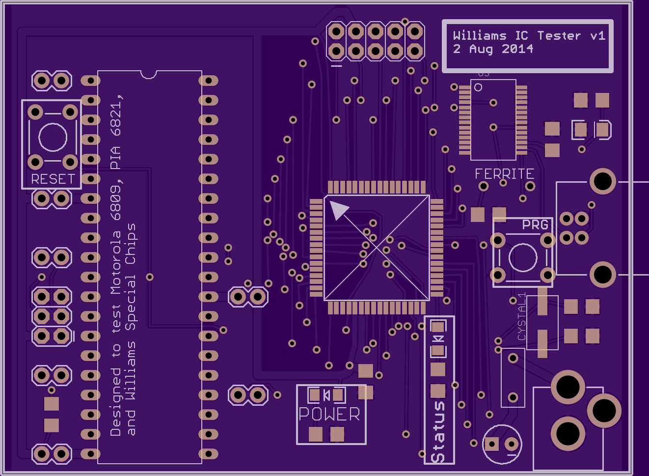
Making a new PCB to test/validate Williams ICs
Star Rider testing has got me so frustrated with suspicions of faulty hardware that I am making a little board to test the big ICs that Star Rider uses: the Motorola 6809E CPU, the Motorola PIA 6821, and the Williams Special Chips.
Friday, July 25, 2014
Troubleshooting Star Rider :)

I hooked up my logic analyzer and my sniffer board tonight to see why STAND BY wasn't working for PR-8210A mode for Dexter rev3. (I was successful, BTW)
See how many relevant components you can name in this picture.
For starters, there is a Dexter rev3 board, an AVR dragon, and my ultimate I/O sniffer board. There are at least 3 other things in this pic that are of interest to laserdisc collectors :)
Star Rider + DEXTER (25 July 2014)
I've got DEXTER rev3 stable enough that I had a chance to try it out with Star Rider. In short, the VBI frame number injection wasn't working at all and it's because of defects in the DEXTER firmware and software. I look forward to fixing these so that I can see if any kind of frame number detection is working.
Also, seeks seem to be getting ignored by the firmware which is odd. There may be a problem with the video squelch and/or the stand-by line. Again, this appears to be a firmware defect.
As you can see, laserdisc video is working but looks pretty bad. I'm not sure if this is just how Star Rider looks (like crap) due to being filtered through crappy ADC/DAC hardware on the expander board or if there's something wrong with the hardware.
And for those still reading (hehe), I did modify two of the ROM ICs so that the game will boot faster and get into the frame seek tests without having all of the inputs hooked up. I modified U52 (on the CPU board) so that the long color tests that start when the game is powered on are completely skipped, and the first ROM test is also skipped. Only the rug pattern tests remains because it goes fast. I happened to have an EEPROM that is pin-compatible with the 2764 used on the original and it seems to be working great. This thing is super easy to reprogram over and over again. I also modified U26 which is a 27128. Unfortunately, I do not have a compatible EEPROM for this one so I ended up reading it (it matches the U26 that is floating around on the internet), erasing it with a UV light, and re-writing it with a modified version of the self-test that immediately skips to the "search to" portion of the DISC TEST. The two former tests (RESET RESPONSE and WALKING BIT test) only test I/O from the main CPU to the PIF board, and don't actually test laserdisc I/O so I am not particularly interested in those for DEXTER development.
Monday, July 21, 2014
Fixing Dexter rev3 hardware defect
So Dexter rev3 has a hardware defect where PR-8210/A mode conflicts with VP-931 mode. I had this crazy idea to remove one of the tiny SMT 2-input OR gates that I have on the board and replace it with a huge 3-input OR gate (DIP version) to fix this conflict. I just soldered it up tonight and it seems to work great! Future updates will have this fixed at the PCB level, so no need for this massive monstrosity on top. But, hey, it works. I really want rev3 to be fully functional no matter how many fixes it needs :)

Friday, July 18, 2014
DEXTER rev3 running at CAX 2014
Here are some videos I took of cabinets running DEXTER rev3 at CAX: Space Ace '91, Dragon's Lair, and Badlands.
Wednesday, July 16, 2014
CAX 2014 Dexter presentation
For those of you who wanted to attend my presentation but could not for whatever reason, here is how it turned out.
Dexter Facebook Page (presentation is near the top)
Dexter Facebook Page (presentation is near the top)
Monday, July 14, 2014
A few short Eugene Jarvis clips from CAX
A bunch of people filmed this entire thing so it is (or will be) available in multiple places but here are just a few short clips I filmed since I was sitting on the front row. You can't tell but the entire room was totally packed with people standing in the back.
Sunday, July 13, 2014
I got to meet Eugene Jarvis and Sam Dicker!
I've become increasingly interested in Williams' early arcade games ever since digging deep into Star Rider's interesting/complicated design so I was quite interested to hear what Eugene Jarvis and Sam Dicker (who worked on the 1980 game, Defender) had to say at California Extreme 2014. After their remarks, I had the opportunity to chat briefly with both of them.
I asked Sam about Rich Witt (who put an Easter Egg in the Star Rider PIF board ROM program) and Chuck Bleich (whose name appears on the schematics). Sam said that he did indeed know Rich but had no idea what had happened to him and was interested if I knew his contact information. I reported that I did not, but I was hoping to one day tell Rich that I found his hidden easter egg inside the PIF board ROM. Sam told me that Chuck Bleich was the guy who designed the hardware.

I also asked Eugene Jarvis about Rich Witt and Chuck Bleich. Eugene told me that he didn't know Rich very well but did know Chuck and also confirmed that Chuck was the guy who designed the hardware. I've sent a few messages to Chuck but so far I have not received any response. I'd love to just chat about the hardware for no other reason than I've spent so much time reverse engineering it. I also told Eugene that I had written an emulator for Star Rider and I asked him about the origins of the special Williams blitter chips. Eugene told me that he thought that Greg Wepner was the guy behind the design of the chips, and I have seen Greg's name on the Star Rider expander board schematic. I think that is pretty amazing to get more insight into the special chips.

I asked Sam about Rich Witt (who put an Easter Egg in the Star Rider PIF board ROM program) and Chuck Bleich (whose name appears on the schematics). Sam said that he did indeed know Rich but had no idea what had happened to him and was interested if I knew his contact information. I reported that I did not, but I was hoping to one day tell Rich that I found his hidden easter egg inside the PIF board ROM. Sam told me that Chuck Bleich was the guy who designed the hardware.
I also asked Eugene Jarvis about Rich Witt and Chuck Bleich. Eugene told me that he didn't know Rich very well but did know Chuck and also confirmed that Chuck was the guy who designed the hardware. I've sent a few messages to Chuck but so far I have not received any response. I'd love to just chat about the hardware for no other reason than I've spent so much time reverse engineering it. I also told Eugene that I had written an emulator for Star Rider and I asked him about the origins of the special Williams blitter chips. Eugene told me that he thought that Greg Wepner was the guy behind the design of the chips, and I have seen Greg's name on the Star Rider expander board schematic. I think that is pretty amazing to get more insight into the special chips.
Friday, July 11, 2014


Wednesday, July 9, 2014
5 Dexter boards ready for CAX!
I've tested 5 Dexter rev3 boards as much as I can at home. They all work as far as I can test at home which means Firefox remains untested. I intend to bring all of them to CAX. Now the real test begins :)


Saturday, July 5, 2014
Dexter rev3 Dragon's Lair test
Now that I have my rev3 Dexter board assembled, it is time to test it out on my Dragon's Lair cab.
Dexter components labeled

In case anyone is curious, here is a brief description of the integrated circuits on the board and their purpose. I labeled these really quickly so they are a little hard to read.
- Voltage converter: convert between 5V and 3.3V for I/O between 5V AVR and 3.3V raspberry pi.
- micro 2: Auxilliary AVR microcontroller. Injects frame number into video signal for PR-8210/A games.
- sync separate: grabs vertical sync and horitzonal sync signals from video signal to that AVRs know when frame starts and which line number is active (so it can inject frame number into video signal)
- video mux: so that video can be muted during seeks and frame number can be injected into video signal
- tri-state buffer: to transform the centronics-24 connector so that it can support PR-8210A mode. Also to squelch AUX AVR transmit (see OR gate 1). The main AVR and aux AVR communicate with each other through TX/RX lines but the main AVR's TX/RX lines are also used to talk to the serial1/2 ICs so this is a way to shut down communication if the aux AVR is inactive without shutting the aux AVR down entirely (Warren pushed for this feature strongly. I was okay with just putting the AUX AVR in reset mode when it was not being used)
- OR gate 1: to squelch Auxilliary AVR's transmit line if either of the serial ICs are active (to avoid conflicts)
- OR gate 2: to merge PR-8210A "remote control" and "remote control enable" signals into a single signal since we ran out of pins on the main AVR. Also improves performance because it means code for main AVR uses less cycles.
- micro 1: main AVR microcontroller, this is where the bulk of the work is done
- BAT1/2: voltage protection in case someone plugs in a serial cable to the DB25 port to ensure that 12V/-12V doesn't make it to the 5V main AVR. Also protects the optocoupler from some idiot plugging in something bad to the PR-8210 port.
- RELAY: solid-state relay to add more protection to the main AVR
- optocoupler: PR-8210 interface that protects the main AVR from someone plugging in something stupid to the PR-8210 port
- serial 1/2: supports serial laserdisc players. The reason there are two of these is that the Sony players are wired backward from the other players so we put two of these on the Dexter board so that the user doesn't have to mess around with null-modem adapters.
- led driver: the board has a lot of LEDs on it and the main AVR can control them all using only 3 pins. Efficient.
Friday, July 4, 2014
First Dexter rev3 prototype fully assembled!
It took a lot longer than my optimistic mind predicted, but I've finished putting the first rev3 board together! And I think it looks awesome! (I am obviously biased)

Wednesday, July 2, 2014
Soldered all of the ICs onto the rest of the Dexter prototype PCBs
I decided that the fastest way to finish all 6 of the prototypes at once is work in parallel, meaning, place one bag of parts on all boards at a time instead of doing one board at a time and having to switch between 50 bags or however many there are. So I decided to solder on all of the ICs this morning. I made great time! Got all 5 boards populated with ICs in 4 hours which is probably a new best time record for me.
ICs populated on top of solder paste.

All finished with all solder bridges removed. I am sure glad to be finished with this part!

Solder paste applied to all boards. This part took FOREVER!

ICs populated on top of solder paste.
All finished with all solder bridges removed. I am sure glad to be finished with this part!
Tuesday, July 1, 2014
CAX Presentation Schedule Finalized
I have received final confirmation about when the CAX organizers have scheduled my presentation. It's going to be at 11 AM on Saturday (July 12th). I'd sure love to have a lot of people there, so bring a friend :)
I plan on having some prizes available for participants :)
I plan on having some prizes available for participants :)
First Dexter rev3 prototype almost finished
Well, I stayed up way too late working on this, but I've mostly finished soldering! I also learned a few things about skillet temperature, mainly, that it is possible for it to be too hot! Hahaha. I burned the PCB pretty badly but INCREDIBLY, so far everything is still working!
I put solder paste on half of the board, then got scared of accidentally nudging an IC out of position and decided to solder the ICs on first before continuing with the rest of the easier parts.

The IC soldering went incredibly well. I only had about 3 solder bridges. The middle of the board has started to turn brown at this point but I wasn't worried. I knew I just had to use less heat on the hot plate the second go around.

The second go around using the hot plate was pretty scary as the board started sizzling, smoking, and turning very dark brown (as you can see). I thought "OH NO, I've ruined the board and all my work is for naught!!" But I decided to solder on a few components to see how bad the damage was and WOW, everything is working so far. Both microcontrollers (AVR 644p and 328p) work, crystals work, and the LEDs (which look horrible after the burn) work too. I don't want to get overoptimistic here, but I think this board might be saved! And don't worry, I will be keeping this one for myself so no one has to worry about getting a burnt prototype board :)


Monday, June 30, 2014
Dexer rev3 : READY TO ROCK (Err ready to solder)
Got the parts!

Got my desk mostly ready...

And most importantly, got the PCBs!!!


New facebook pages
I made a few facebook pages that may be a more convenient way for some people to get news than this blog (although I certainly intend to keep writing here!)
RuleCity LLC (the official company that sells Dexter) : Rulecity Facebook
Daphne Emulator : Daphne Facebook
Dexter Laserdisc Replacement : Dexter (Facebook)
RuleCity LLC (the official company that sells Dexter) : Rulecity Facebook
Daphne Emulator : Daphne Facebook
Dexter Laserdisc Replacement : Dexter (Facebook)
Friday, June 27, 2014
the PCBs are on their way to me as we speak
Just got this email from oshpark.com :
"Hi Matt Ownby!
Your Dexter rev3a boards are on their way!
Your boards have been depanelized and shipped to you"
Thursday, June 26, 2014
Dexter rev3 pricing announced (AND PROTOTYPES FOR SALE)!
Last updated: 9 June 2015 (updated status of Dexter's compatibility)
PRICING FOR DEXTER
At CAX 2011, during my presentation, I told the crowd that I estimated that Dexter's final price would be about $400. After talking to the company that is going to manufacturer the Dexter boards, I am pleased to announce that we are able to offer Dexter for a lower price than the initial estimate if it is bought in bulk.
The prices as of now will be:
$399 for 1 Dexter complete package*
$374/each for 2 Dexter complete packages
$349/each for 3 Dexter complete packages
$324/each for 4+ Dexter complete packages
PRICING FOR LASERDISC IMAGES
I've signed a deal with Digital Leisure, the copyright holder of many laserdisc games, to distribute their titles with Dexter! Here are the prices:
Dragon’s Lair $19.99
Space Ace $19.99
Dragon’s Lair 2: Time Warp $19.99
Dragon’s Lair Trilogy [DL/SA/DL2] $39.99
Mad Dog McCree $12.99
Mad Dog 2: The Lost Gold $12.99
The Last Bounty Hunter $12.99
Crime Patrol $12.99
Crime Patrol 2 : Drug Wars $12.99
Who Shot Johnny Rock $12.99
Fast Draw Showdown $12.99
Old West 3-Pack [Mad Dog 1, Mad Dog 2, Bounty Hunter] $28.99
Crime Fighter 3-Pack [Crime Patrol 1 & 2, Johnny Rock] $28.99
Time Traveler $9.99
Thayer’s Quest $9.99
NOTE : These laserdisc images will be copy protected!
PROTOTYPES
In addition, I am currently manufacturing (and negotiating further manufacturing for) a small number of prototype rev3 boards to do the final testing to make sure we can clearly communicate to customers exactly what this board is going to be able to do at launch.
We are going to offer these prototype complete packages for $350 each (limit 1 per customer unless there are a bunch of extras). Here is the scoop about the prototypes:
- They may have very minor design defects but this is very unlikely at this stage (this is at least the 4th iteration of the current design).
- I cannot offer refunds, only help in fixing problems. However, previous prototype runs have been very successful, and there are many youtube videos showing the prototypes in action (which I can link to if anyone has a concern) including videos of Firefox, Dragon's Lair, Space Ace, and Thayer's Quest in action.
- Use this spreadsheet to see exactly what player types and games are currently supported. Additional player types MAY work in the future with firmware updates that we provide (we plan on this but cannot guarantee it. what you see today is what you get today.)
- I will pre-install certain licensed laserdisc images for the prices listed above.
Pioneer LD-V8000 will not be officially supported by Dexter rev3
I forgot to announce this, and I know that this will be disappointing to some of you, but I am not going to be officially support the Pioneer LD-V8000 player in Dexter rev3. The problem is that, as I understand it, Galaxian 3 (the only game that actually uses it that I am aware of) requires two LD-V8000's to be synced to each other and there is no way for Dexter rev3 to support this right now. I may still add unofficial support for the LD-V8000 later via add-on card that will not support seeking but still can be controlled via the serial connector.
Tuesday, June 24, 2014
CAX: It's official!
Not that anyone was doubting, but I am officially on the list :)
Just got this email:
Just got this email:
Speakers
We are working on finalizing the speakers for the show. Below is a teaser list of who’s coming (subject to change):
Eugene Jarvis will return to CAX to discuss his legendary work in creating some of the greatest arcade games ever made. Learn about Defender and his many other contributions to gaming.
Larry Rosenthal, creator of the Vectorbeam system, will be on hand to discuss his technical achievement and shed some light on the realities of his experience bringing it to the arcade.
Skit-B Pinball will discuss their creations and future plans. You won't want to miss this seminar - they plan to raffle one of their creations to someone attending the presentation!
Matt Ownby will discuss Dexter, a project keeping classic laser games alive.
Roy "Mr. AWESOME" Shildt will discuss the game Missile Command, as will Dwayne Richard, who has created a documentary on proper play settings.
A panel of Sente employees will convene to discuss the history of the company.
PPM will be making their case for a pinball museum at the Alameda Carnegie Library.
Sunday, the Film Festival returns with Richie Knucklez, King of Arcades, a piece on Wade Krause's contributions to the FAILE BAST Deluxx Fluxx Arcade, and a number of shorts.
Also, I didn't know that Eugene Jarvis was gonna be there. I definitely want to see what he has to say!
Saturday, June 21, 2014
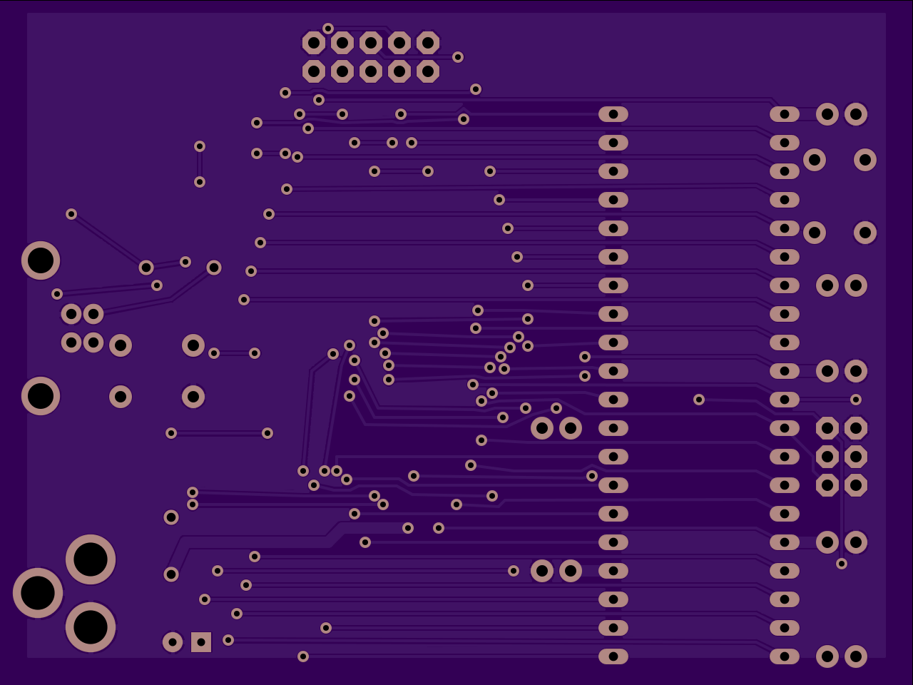
High res render of Dexter rev3
Here is a high resolution (1200 dpi) rendering of the current Dexter rev3b layout for anyone who is curious.

Tuesday, June 17, 2014
Dexter rev3 : FEAST YER EYES (spoken with Scottish accent)
Dexter rev3 is ready! I've ordered 6 PCBs from oshpark.com for testing. If all goes well, I will start taking orders and mass produce these things. I have cut it really close as it is 17 June so there is no guarantee that I will have enough time to get the board back from oshpark.com and be able to get it assembled in time for CAX on 12 July, but I am going do my best!
While it is probably difficult to judge, this represents a massive improvement over Dexter rev1 and rev2 and is quite a bit smaller in size than rev2. I crammed the parts as tightly as I possibly could. There are still some empty spaces but this was definitely a growing experience for me.
While it is probably difficult to judge, this represents a massive improvement over Dexter rev1 and rev2 and is quite a bit smaller in size than rev2. I crammed the parts as tightly as I possibly could. There are still some empty spaces but this was definitely a growing experience for me.
I am very excited!


Monday, June 16, 2014
Dexter WIP 16 June 2014
I've made a ton of progress. Still got a few components to place, but as you can see, it is looking awesome!:)

Thursday, June 12, 2014
I've finally started routing Dexter rev3

I just routed the lower left corner of the rev3 Dexter board. It was quite challenging but I am quite pleased with how it turned out. As you can see, I packed everything in very tightly and still managed to have 4 sets of pin headers in there and a ground plane. The LM1881 and video mux ICs are also in there.
Fully automated Dexter setup inside my Dragon's Lair
So the USB flash drive I purchased seems to be working perfectly. I think we have a winner!
I hooked it up to my cabinet in the garage and let my kids play it. My oldest son is the same age that I was when I first saw the game which is making me feel _very_ nostalgic!
I hooked it up to my cabinet in the garage and let my kids play it. My oldest son is the same age that I was when I first saw the game which is making me feel _very_ nostalgic!
Wednesday, June 11, 2014
Evaluating USB flash drive for use with Dexter
Dexter is getting close to being available to public (yes, really!).
As part of hurrying to finish this effort, I need to decide what kind of USB flash drive to include with Dexter (I am leaning against putting everything on the SD card due to reliability issues).
I purchased a Sandisk Ultra USB v3.0 flash drive (16 gig) which claims to be able to read 80 megabytes/second and I am going to try it out in my Dragon's Lair cabinet soon to see how the performance is. It only cost $12 so it is a good option to keep costs down for Dexter customers :)
Here is a benchmark I ran on it (using USB v2.0 interface, so the max speed is bottlenecked by the bus limitation). It seems to choke when reading smaller chunks than 64kb at a time which shouldn't be a problem.
Wednesday, June 4, 2014
Dexter rev3 WIP 4 Jun 2014

In addition to improving performance so that the AVR doesn't have to think about this logic, it also avoids using an extra pin on the AVR (which is pretty much full as it is).
The OR gate essentially turns pins 9 and 10 into a single pin that is only low (active) when the game hardware is really trying to send a command to the player. And the thing is so tiny (2mm) that one could sneeze and never find it again if one isn't careful.
Looks like I will be presenting at CAX
I just got official word that I will be presenting at CAX 2014. If anyone has anything they specifically want me to talk about that they would find interesting, I am inviting feedback starting immediately. Commenting on this blog post is one way you can get word to me :)
Tuesday, June 3, 2014
Dexter rev3 progress

I also tried to pack in the resistors to reduce the board size. Once I add all of the new components that I want, I will probably start routing. I also am seriously considering reducing the IC size of the MAX222 and LED driver ICs in the interest of shrinking the board size some more.
Wrote my first Java GUI app
I've been looking for an excuse to learn Java for years now and I finally found one. Over the weekend, my ISP was flaking out on me, so I decided to write an app to monitor how often my ISP forcefully disconnected my open TCP connections (which is really annoying for IRC usage). I initially wrote the app in C# as that is what I am more familiar with, then ported it to Java, using SWT for the UI.
As you can see, there is a defect in the Java version with the time counter, but otherwise it seems to work pretty well.

UPDATE: Wow, just tried to see how hard it would be to get the Java version running on linux and it turned out to be pretty easy! I am impressed!


As you can see, there is a defect in the Java version with the time counter, but otherwise it seems to work pretty well.
UPDATE: Wow, just tried to see how hard it would be to get the Java version running on linux and it turned out to be pretty easy! I am impressed!
Friday, May 30, 2014
I will be at California Extreme 2014!
Barring unpreventable emergencies (such as my unborn son coming very prematurely), I will be at California Extreme 2014 on July 12th. I've contacted the CAX organizers and proposed that I give another presentation like I did 3 years ago (wow, can't believe it's been that long!) and now they are (presumably) considering it. So this may or may not happen. I am keeping my fingers crossed because I had a lot of fun last time and have some new cool stuff to talk about this time regarding Daphne, Dexter, and more :)
I will really try to have a Dexter rev3 prototype on hand to show off at the show, and to install in available laserdisc game cabinets at the show for those who are interested. That means I have about a month to get the design finished, get the PCBs fabricated, and get the board assembled. It's crunch time! :)
I will really try to have a Dexter rev3 prototype on hand to show off at the show, and to install in available laserdisc game cabinets at the show for those who are interested. That means I have about a month to get the design finished, get the PCBs fabricated, and get the board assembled. It's crunch time! :)
Saturday, May 24, 2014
Fixed Daphne 64-bit overflow bug
So, not too long ago, I modified the way vertical blanking timing is calculated to be very accurate. I was working on Star Rider emulation, so I didn't spend that much time thinking about overflow issues when designing this. Well, it turns out that my initial design was pretty prone to overflow, plus it was computationally expensive. Here is how I calculated CPU cycle counts relative to vertical blanking timing:
#define DIVIDER 63000000
void VblankTimer::OnTopFieldVblankStart(unsigned int uFrameIdx)
{
// this operation is essentially [lines finished] * [microsecond / line] * [ cycles / microsecond]
// (uFrameIdx * 525) * (4004/63) * (cpuHz / 1000000)
// TODO : would floating point math be faster here?
// determine the base cycle count using a VERY accurate, self-correcting, and expensive method
m_u64Line1StartCycle = (uFrameIdx * 525);
m_u64Line1StartCycle *= 4004;
m_u64Line1StartCycle *= m_u32CpuHz;
m_u64Line1StartCycle /= DIVIDER;
// set up next event
this->m_pCallback->RegisterCpuEvent(m_u64Line1StartCycle + m_u32TopVblankEndCycleOffset, OnTopFieldVblankEndCallback, this);
}
#define DIVIDER 63000000
{
// this operation is essentially [lines finished] * [microsecond / line] * [ cycles / microsecond]
// (uFrameIdx * 525) * (4004/63) * (cpuHz / 1000000)
// TODO : would floating point math be faster here?
// determine the base cycle count using a VERY accurate, self-correcting, and expensive method
m_u64Line1StartCycle = (uFrameIdx * 525);
m_u64Line1StartCycle *= 4004;
m_u64Line1StartCycle *= m_u32CpuHz;
m_u64Line1StartCycle /= DIVIDER;
// set up next event
this->m_pCallback->RegisterCpuEvent(m_u64Line1StartCycle + m_u32TopVblankEndCycleOffset, OnTopFieldVblankEndCallback, this);
}
As I show in my comments, the basic algorithm to compute the CPU cycle count for when vblank of the top field should begin is:
currentFrame * 525 * 4004 / 63 * CpuHz / 1000000
Now, one can plug this into a calculator and get a pretty accurate floating point result. For example, if the cpu frequency is 1 MHz (1,000,000 Hz) the answer would be 0 if the currentFrame is 0, or 33,366.666666 or 33,367 if one rounds it up.
However, doing math the way a typical calculator does it in this program is expensive, and on CPUs such as ARM that handle floating point operations (ie fractional numbers) poorly, doing floating-point math brings the CPU to its knees.
So it is much faster to do integer math.
However, when doing integer math, the result of any math operation discards any fraction. So 3/2 is not 1.5 but instead 1. That means in order to get the best accuracy, division should be saved until the last possible moment.
This means that the order that one would perform the math would be:
currentFrame * 525 * 4004 * CpuHz
and then divide the whole thing by 63 * 1000000
This makes for a very large number before the division takes place!
I was noticing that Dragon's Lair was locking up after running for a while (meaning almost 24 hours) and I tracked it down to when the currentFrame value is greater or equal to 2,193,848. At 29.97 frames per second, this is 20.33 hours.
2,194,847 is still manageable. 2194847 * 525 * 4004 * 4000000 (Dragon's Lair CPU speed) is 0xFFFFFF20BC896C00 in hex (64-bit number).
However, 2194848 * 525 * 4004 * 4000000 when performed on calc.exe is 0x1DE62BA75C8000 in hex (64-bit number) which is less than the previous result. This means that overflow has occurred. So the solution here is to either try to do 128-bit math which is expensive no matter what or try to find another way to solve this problem :)
I decided that the best solution to avoid overflow issues like this is to get rid of the multiplication entirely and just use addition (adding onto previous result each new frame). This is dangerous to do with integer math because it can lead to greater and greater inaccuracy over time.
However, I did some experimentation and found a pattern with part of the calculation. currentFrame * 525 * 4004 / 63 has a repeating pattern which can be mimicked with integer math:
Frame: 0, time is 0.000000
Frame: 1, time is 33366.666667
Frame: 2, time is 66733.333333
Frame: 3, time is 100100.000000
Frame: 4, time is 133466.666667
Frame: 5, time is 166833.333333
Frame: 6, time is 200200.000000
Every 3rd value is a whole number.
I observed that this pattern can be approximated (without loss of accuracy over time) by adding 33367, 33366, and 33367 over and over again.
I've now implemented a new system that does just this: adds 33367,33366,33367 after a one-time calculation of multiplying these numbers by cpuhz/1000000. This now is much faster, doesn't lose accuracy, and will still work naturally when the total cycle count overflows (which, since I am using a 64-bit number, will take quite a while to do).
Subscribe to:
Posts (Atom)